An outdoor enclosure, a four-louvre Stevenson screen and nearly two weekends of small fixes that only became obvious once I had the parts in my hands.
Adam supplied and installed my first Weather Guardian unit in an off-the-shelf electrical box. Water got in, so he gave me an AI-designed replacement enclosure to print and test. I printed it and tried my circuit board in it. The board didn’t fit, and the support material on the lid wouldn’t budge. That’s when I started redesigning the enclosure around the hardware I actually had.
The electronics needed to stay dry, while the temperature, humidity and pressure sensor needed outside air and some shelter from direct sun and rain. A cable had to connect the two through the case wall.
I spent most of two weekends on it. The job grew from getting a circuit board into a case to working out how to mount the sensor, seal two cable entries and fit a solar panel. I kept coming back to the real parts on the bench. A cable bend or a spanner that couldn’t reach a nut could send me back to CAD.
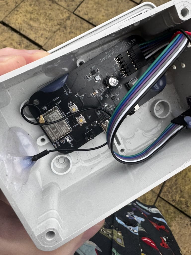
The original electrical box Adam supplied and installed, with water visible around the board and wiring. Photo by Matt Charlton.
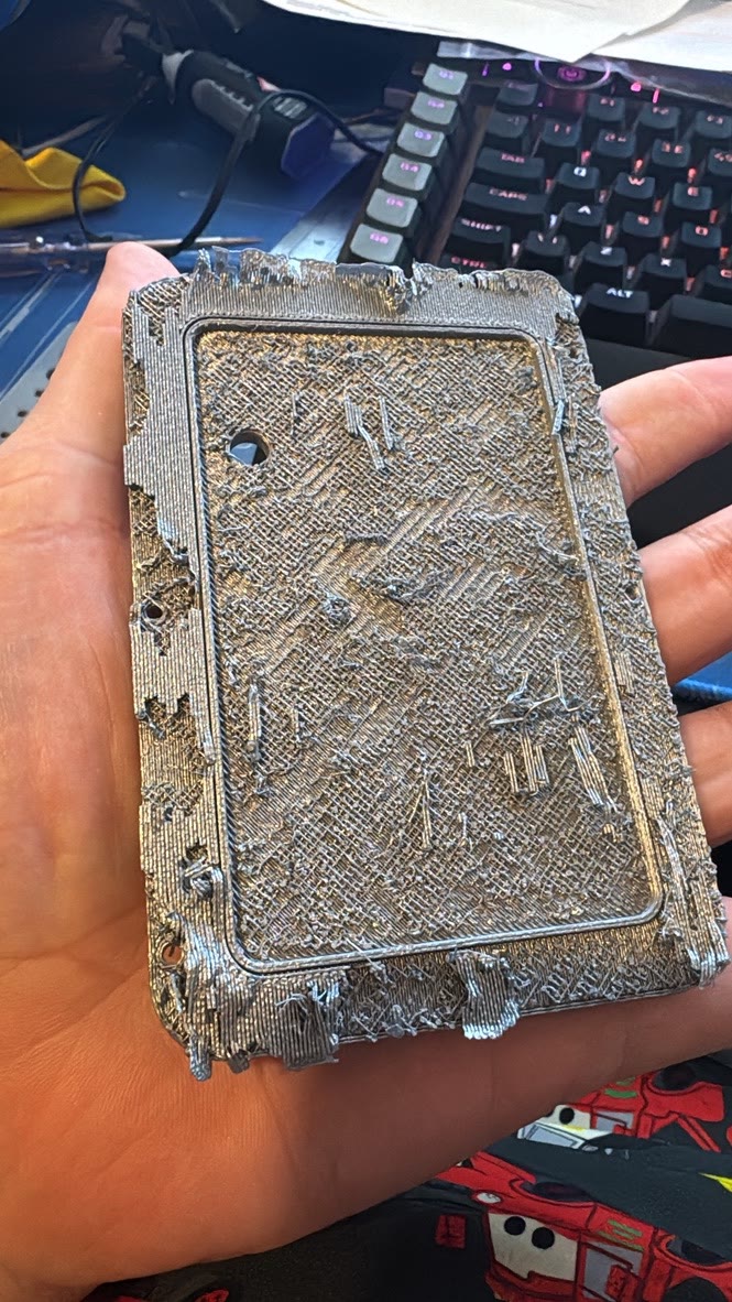
The lid from the AI-designed replacement Adam gave me to try. The support material wouldn’t budge. Photo by Matt Charlton.
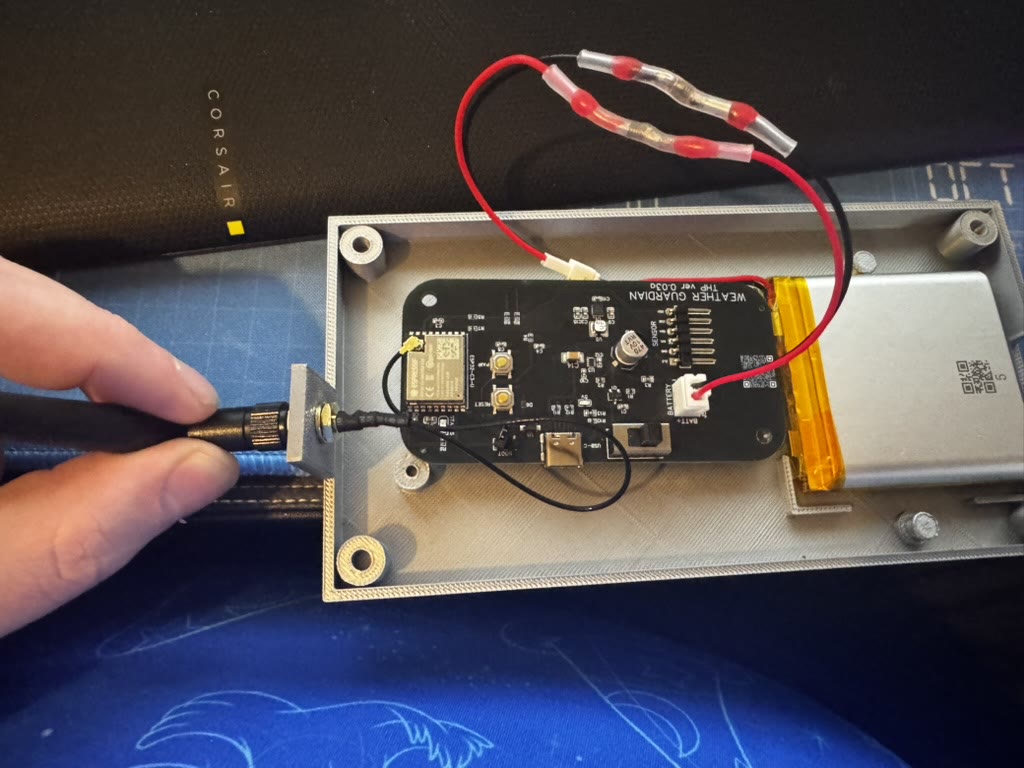
Checking the board, battery and aerial together in an early tray. Photo by Matt Charlton.
Making room for the actual hardware#
Once I had the board in a tray, I could start checking all the space the outline of the PCB had left out. The aerial connector had to pass through the case wall, the ribbon had to reach the header without being pinched, and there had to be room for the battery and its leads. I tried both the flat LiPo and an AA holder in the early prints. The LiPo got a recess and a printed retainer across it, so I could take it out again when it needed charging.
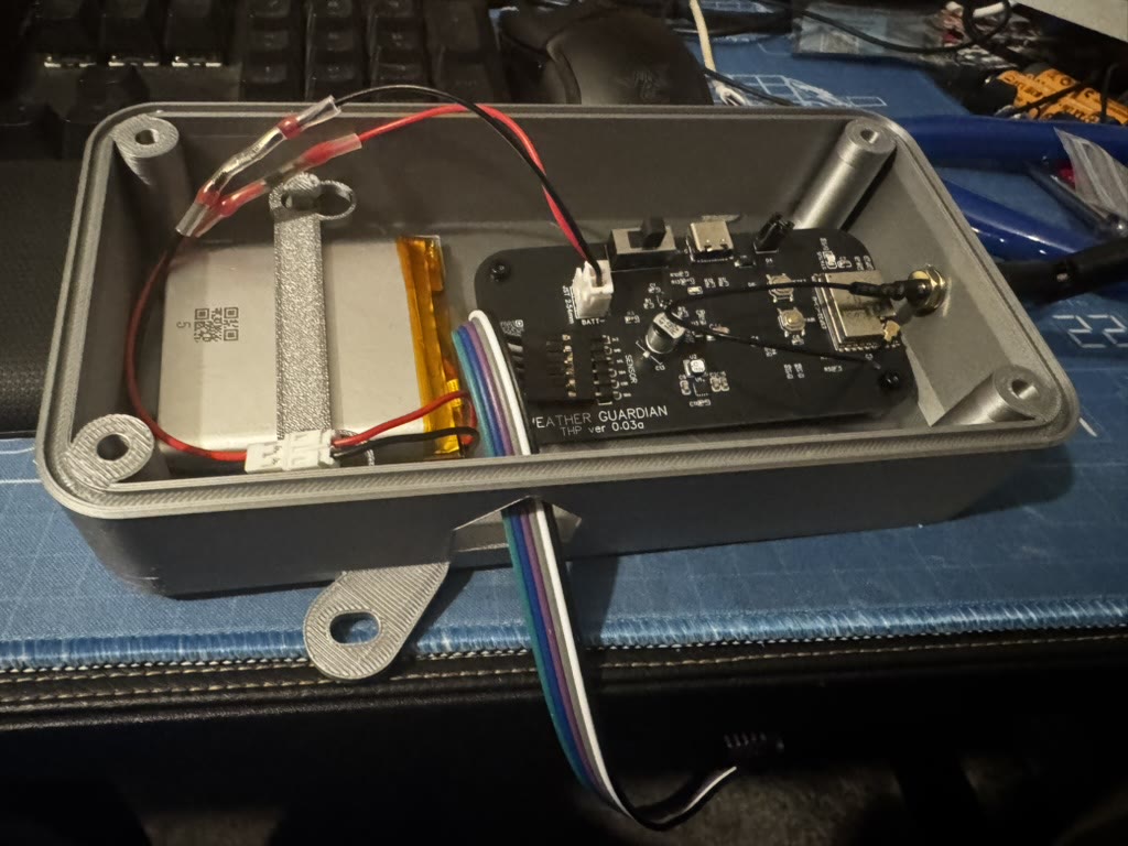
The silver prototype with the battery retainer fitted and the flat sensor ribbon coming out through the side. Photo by Matt Charlton.
A gasket that would stay put#
With the layout sorted, I could work on closing the case. The lid seals against 2 mm foam cord. On the early prints the cord could lift out of its groove while I was assembling the case, so I printed short samples with different groove widths. The 1.8 mm groove held the cord better during handling and went into the next case. Testing a little strip was a lot quicker than printing another whole tray.
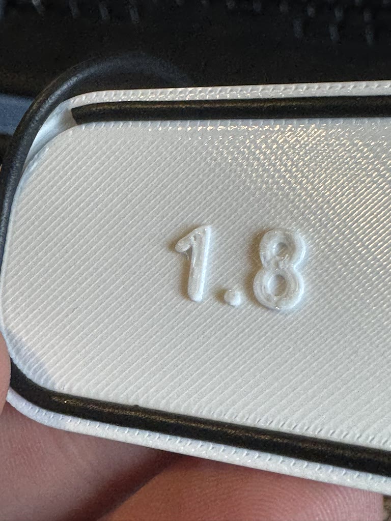
The 1.8 mm groove coupon let me check whether the foam cord would stay in place during assembly. Photo by Matt Charlton.
The first sensor entry clamped a flat ribbon. An oversized heat-shrink sleeve stayed bulky and stiff even after shrinking, so I took it off. A tighter marine-grade sleeve and a 2 mm silicone strip gave the clamp a much firmer grip. There was still a second interface to deal with, where the clamp flange met the case. I found that gap on the assembled print. Squeezing the cable and closing the joint against the case wall were two separate jobs.
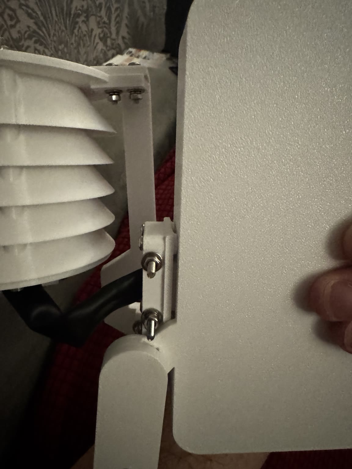
The original ribbon clamp on the bench. The dark line along the case wall is where the flange gasket should sit. Photo by Matt Charlton.
Getting the sensor out beside the case#
I had 100 mm of sensor lead outside the enclosure. That made the route to the sensor a real constraint. I worked through an under-case bracket and a longer carrier before settling on a side arm. The V17 screen uses four overlapping louvres with integral posts, so there are no loose spacers to line up. The sensor sits inside the louvres, with a small shroud below to shelter the cable.
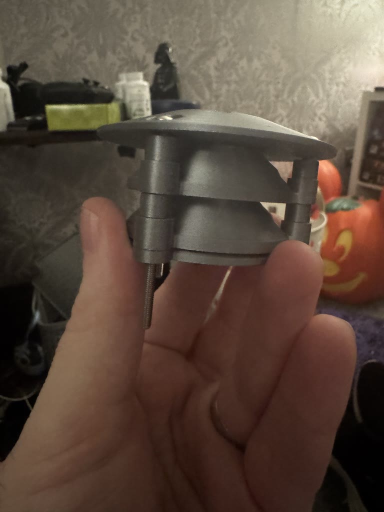
An early two-ring screen trial with separate spacers. The later four-ring design built the spacing into the louvres. Photo by Matt Charlton.
The fence exposed another assumption. The upper fixing ear missed the timber on my narrow post, so I used the lower fixing on that installation. The later solar tray got strap ears for mounting around a post. Back at the bench, I also revised the sensor carrier with vertical tie slots after finding how awkward the original ones were to thread. And when support material blocked an ear bolt on Adam’s print, I trimmed the support settings back to what the parts needed. The four louvres print without supports.
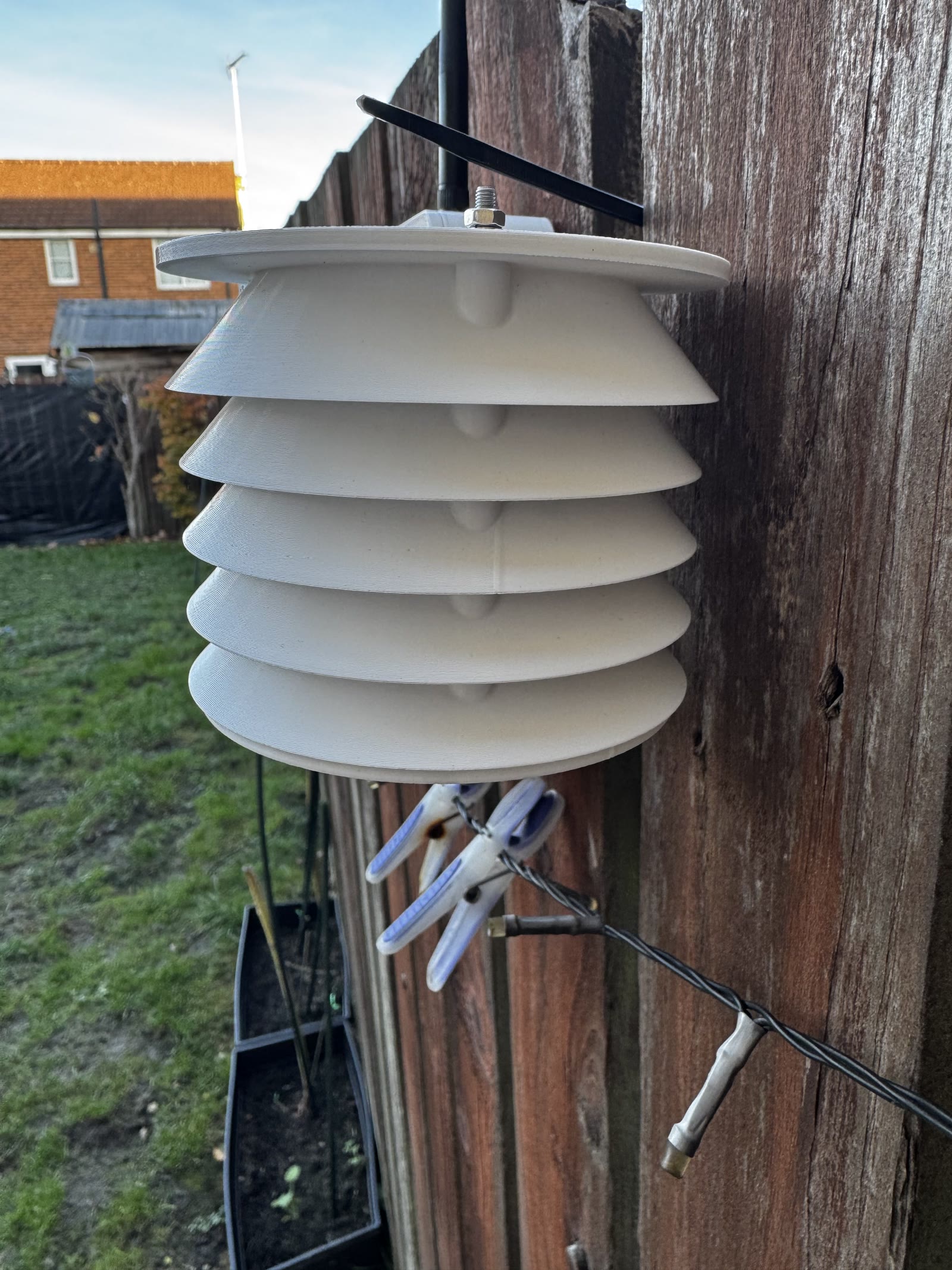
The four overlapping louvres and the short side arm that holds the screen alongside the box. Photo by Matt Charlton.
A smaller solar board and a nut that kept spinning#
The solar version used a smaller circuit board with a single mounting hole, so I designed a removable cradle that reused the two mounting points already in the case. The solar battery holder fitted across the tray, with room for its leads at both ends.
The first cradle was a reminder that having the board dimensions in CAD only gets you so far. The board was about 82.8 × 46.0 mm, but the usable opening in the printed cradle was smaller in both directions. The board wouldn’t sit down in it, and the first design had no screw mount under the board’s single hole. I went back to the measured board, checked where the solder joints sat on the underside and worked on the cradle separately so I could try the next revision without printing another case.
Getting a screw through the board was only half the job. An early slotted holder let the tiny M2 nut spin as I tightened the screw. I printed a strip with three hex pockets. The nut wouldn’t seat in the 4.0 or 4.1 mm pockets in that PLA print. The 4.2 mm pocket took it and stopped it turning. I carried that shape into the cradle and checked the screw position on the real board.
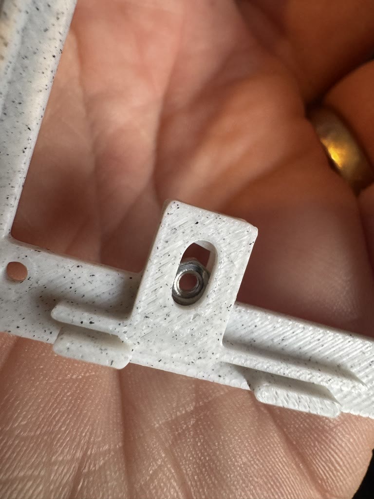
The earlier slotted nut holder on the bench. The fixed hex pocket came after this trial. Photo by Matt Charlton.
Two round glands and a kitchen-tap test#
Solar power also meant adding a second lead through the case. I prototyped a PG7 cable gland for that entry and moved the sensor entry to a PG7 as well. The gland squeezes around a round cable, and a washer seats against the case wall. Getting that washer a flat seat and leaving enough thread and room inside to tighten the locknut took a few prints.
I printed three small wall samples with the same nominal bore and different thicknesses. At 3.0 mm I couldn’t fit the gland. At 2.6 mm the locknut skipped. At 2.2 mm the fitting seated properly in the sample. That gave me a thickness to work with, and a flat seat and room for a spanner still mattered once the hole was in the case. On one full print the relief behind the gland ran past the raised pad and left an opening along its edge. That was the reason for extending the pad.
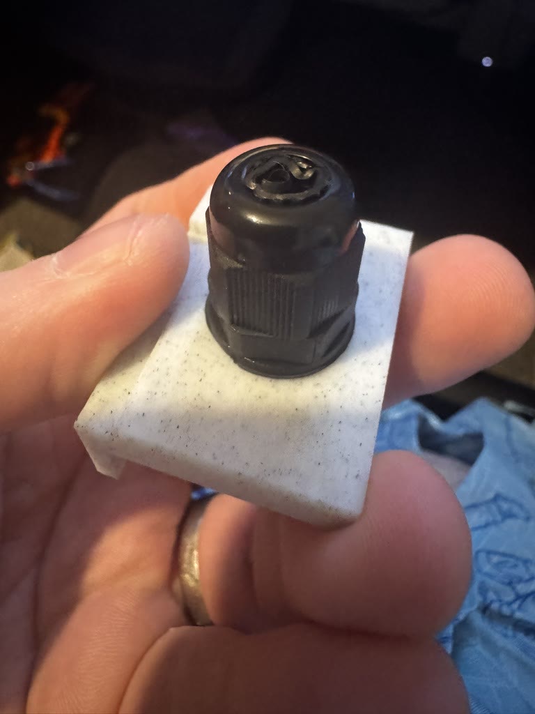
A small printed wall section for checking how the PG7 gland sat in the case. Photo by Matt Charlton.
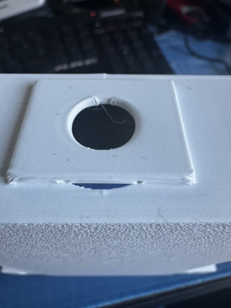
The opening below the power-entry pad on an earlier print. The next revision extended the pad over the recess. Photo by Matt Charlton.
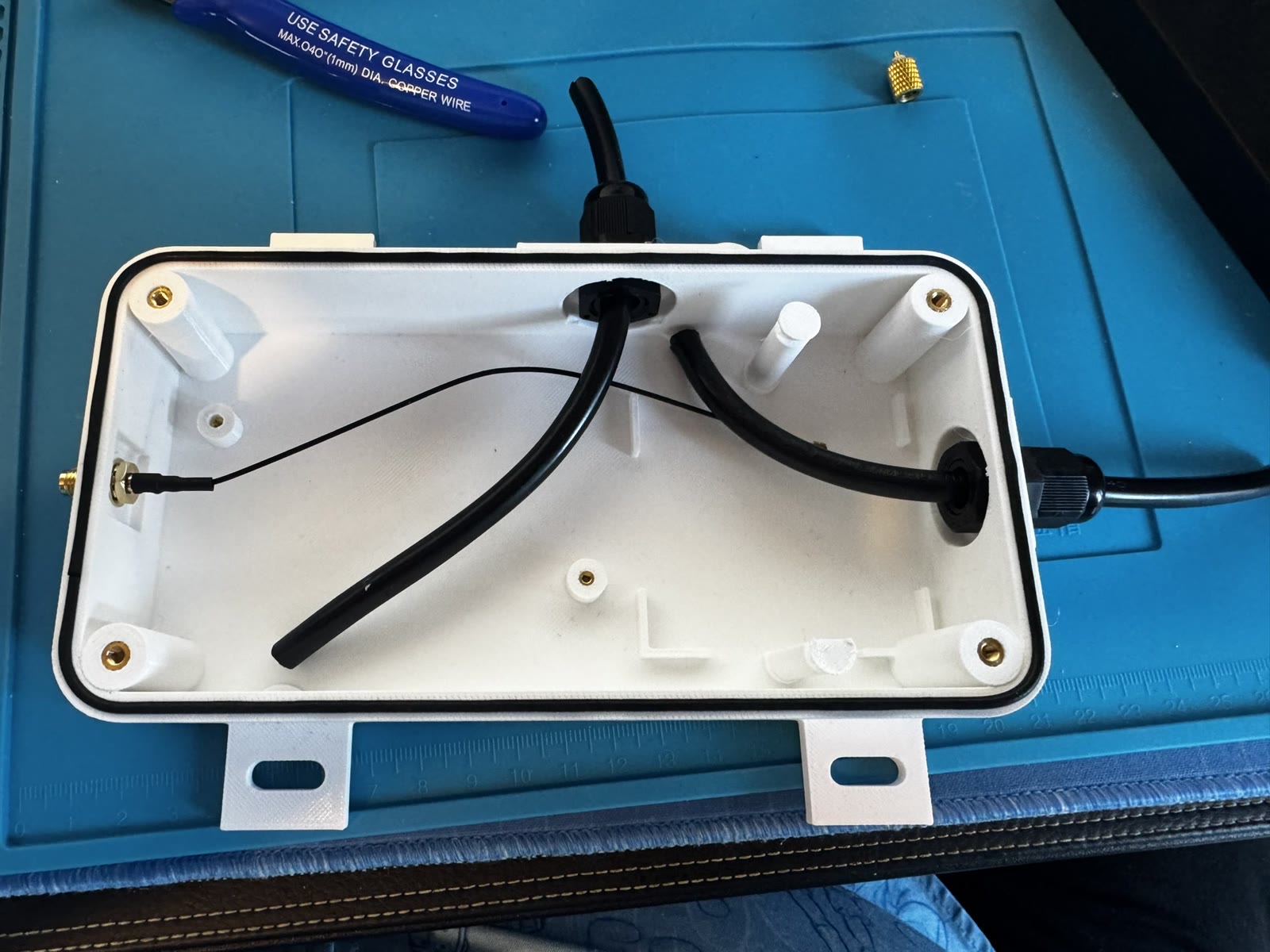
The dual-PG7 solar enclosure opened up to show the lid cord and both cable paths. This photo shows the assembly, rather than the tissue result. Photo by Matt Charlton.
For the assembled solar enclosure test, I fitted both jacketed cables, the aerial and the portrait lid with its cord gasket. I put three dry tissues inside and ran the closed case under the tap, wetting all sides and entry points. When I opened it, all three tissues were dry. Separately, the outdoor enclosure was dry inside when I brought it in for rehousing. The tap result applies to the solar assembly as tested. Long-term exposure and the separate battery-only PG7 tray are still open checks.
There was one more cable twist after that. A hand-terminated round Cat6 lead gave readings at first, then went intermittent after reassembly. I went back to the original ribbon conductors, separated them, gathered them into a round bundle and fitted it through the PG7 while the heat-shrink was still pliable. The sensor started reporting again. The revised lead still needs its own tissue test.
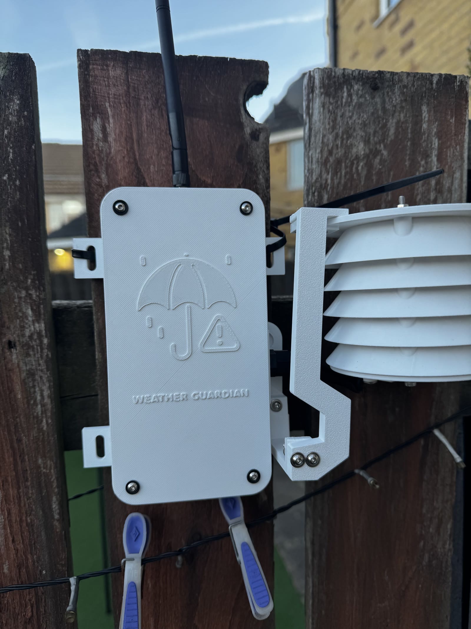
The enclosure and Stevenson screen on the fence. The cable entry is out of view. Photo by Matt Charlton.
A panel on the bench and three print projects#
The panel mount had its own round of trial prints. The panel fitted the first bezel, but the snap arms broke and the bezel obstructed the cable outlet. I kept the panel pocket and changed how the two halves went together. The next version used screws, gave the panel a ledge to sit on and brought the cable out through the rear cover. I then assembled the bezel, cover and post backplate together.
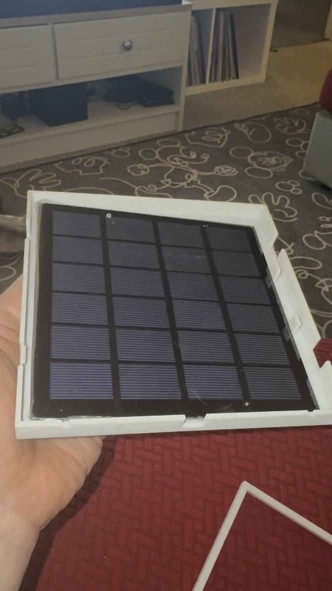
Checking the solar panel in its printed frame before final assembly. Photo by Matt Charlton.
I soldered on the 15 m lead and measured nearly 6 V at the far end under a SAD lamp. I still needed a charging test under load. For that evening, it was good to see the panel, screen and enclosure together on the bench.
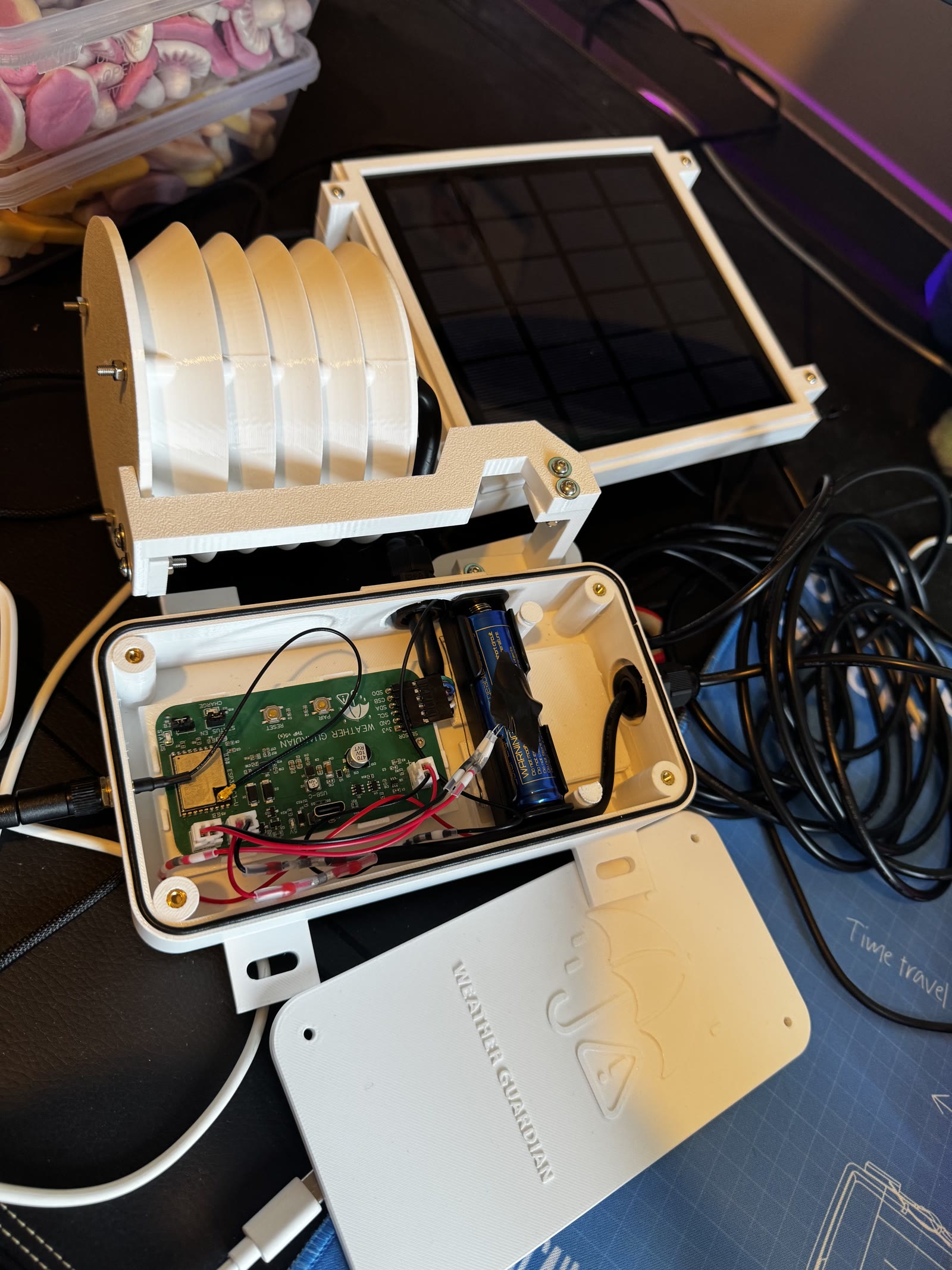
The solar enclosure, Stevenson screen and panel together on the bench. Photo by Matt Charlton.
Print files#
The three print projects are on MakerWorld.
- Weather Guardian Standard Enclosure 1.0 for the battery-only build.
- Weather Guardian Solar Enclosure 1.0 for the dual-gland enclosure and solar panel mount.
- Weather Guardian Stevenson Screen 1.0 for the four-louvre screen and side arm.
You can see live sensor readings on the Weather Guardian sensor map.
Interested in how Weather Guardian could help you or your business to monitor realtime weather readings and automate your processes?